Enhance your Fluid Dispensing Systems process with our help.
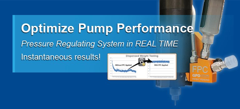
Increase Fluid Dispensing Systems Application Productivity & Accuracy.
Global Premium Service & Support.
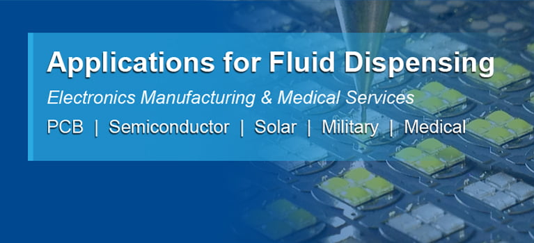
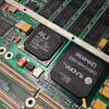
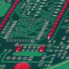
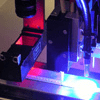
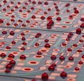
Fluid Dispensing & Solder Paste Jetting
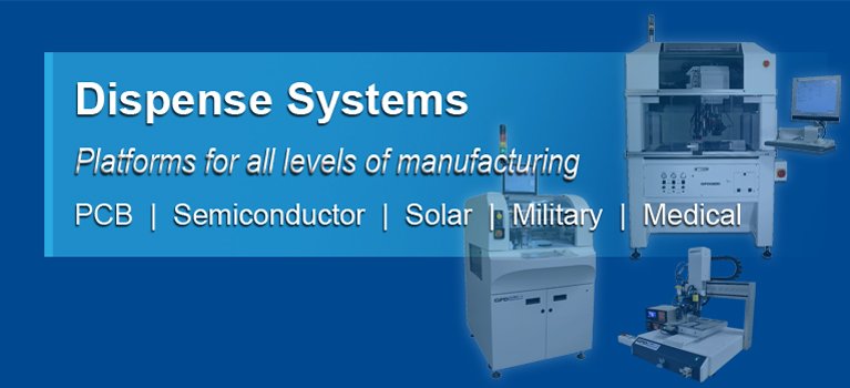
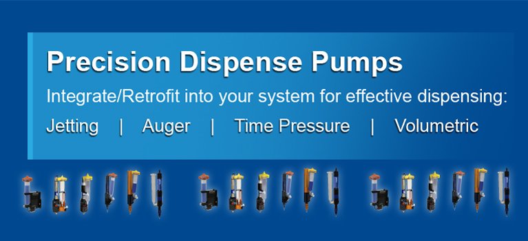
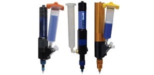
Dispensing Pumps
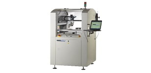
Conformal Coating Machines
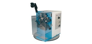
Lead Formers
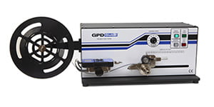
Peel Back Force Tester
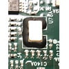
Underfills
Thermal Interface Materials
Solder Paste
Wafer Processing
Solder Mask
Staking
UV Curing
Surface Mount Adhesive
Potting Encapsulation
Trench Filling